



45 Degree Electrofusion Elbow | HDPE Gas and Water, PE100
45 Degree PE100 Electrofusion Elbow - Low-Loss Bends, dn25 to dn900
A single 45° bend changes the line by a quarter of a right angle. That sounds modest until you count how many of them a real alignment needs: two of them, with a length of straight pipe between them, make the same 90° turn that one right-angle fitting makes in one body. The reason to reach for the pair instead of the single fitting is not cost and not convenience - it is the behaviour of the flow and the shape of the trench.
This page treats the 45° bend on its own terms. A hdpe 45 degree bend is a legitimate fitting in its own right for a shallow change of direction, a service connection or a drainage run, and it is also the building block of a swept alignment. A 45 degree electrofusion elbow is a different buying decision from a 45 degree hdpe elbow bought loose from a distributor, and the difference is mostly in the size coverage and the paperwork rather than in the fitting. the building block of a swept alignment. What follows covers the electrofusion joint, the published dimension schedules, the size ranges in each wall series, the geometry you need before you set the alignment out, and the cases where one 45° is the wrong answer.
How the Weld Is Made, and What Holds It

The 45° body: two electrofusion sockets set at 135° to one another.
To answer what is a 45 degree bend in one line: a pipe fitting whose two sockets leave the body at 135 degrees to each other, so the flow direction changes by a quarter turn. The fitting arrives with a resistor wire moulded into each socket and a barcode on the body. The barcode is the part that matters operationally: it carries the mould identity, and the electrofusion machine decodes it to select an energy profile. A dn200 45° bend and a dn200 right-angle fitting are different moulds with different programmes, and the machine will refuse a barcode that does not match the parameter set it is holding.
When the cycle runs, current passes through the wire, the polymer around it melts, and the socket expands against the pipe it has been pushed over. The joint that results is not a mechanical connection in the usual sense - there is no gasket and no thread - it is a continuation of the pipe wall itself. That is why the fusion face has to be clean and dry and scraped, and why the same fitting cannot be reused once it has been fused.
A 45° fitting and a 90° fitting differ in one respect that a installer notices immediately: the two sockets on a 45° body are set at 135° to one another, not at 90°. That geometry is what makes the part difficult to align by eye and easy to align with a protractor, and it is also why the two fittings of a swept turn must be set relative to a known straight rather than relative to each other.
What the Fitting Is
The first block of the data sheet is the identity of the part and the limits of the range. Read the size line before anything else: SDR11 availability and SDR17 availability do not overlap across the full range, and a specification that says "45° elbow, dn25 to dn900" is not achievable in one wall series.
Fitting
HDPE electrofusion elbow, 45 degree
Change of direction
45 degree - sockets set at 135° to each other
Resin
PE100 polyethylene, 100% virgin resin, no regrind
Size coverage
dn25 to dn900 - in SDR11 to dn400, in SDR17 to dn900
Pressure class
PN16 in SDR11 sizes; PN10 in SDR17 sizes
Standards met
ISO 4427 and EN 12201 for water; ISO 4437 and EN 1555 for gas; GB 15558 for Chinese gas networks
How It Behaves in Service
The second block covers what the fitting does once it is in the ground: how it is welded, what it costs the flow, what it is approved for, and how long it is expected to last. These are the lines a specifier usually wants and rarely finds on a data sheet.
Weld process
Electrofusion - the weld cycle is carried on the fitting barcode and runs on any compatible EF machine
Head loss at the bend
About 0.2 velocity heads per bend; a pair with a straight between comes in near 0.4, against 0.6 to 0.9 for a long‑radius right angle
Pattern of use
One bend for a shallow change of direction; two with a straight between for a full 90° turn
Service media
Natural gas, LPG and biogas; potable and industrial process water
Colour and marking
Black body, UV stabilised; gas‑grade yellow marking available on request
Approvals held
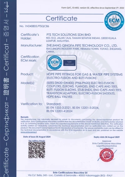
ECM type approval to DN400, with elbows named in the scope of the certificate; ECM attestation to DN1200 for markets outside the EU; WRAS applies to the injection moulded parts
Private label
OEM and ODM - your logo moulded into the body; cartons and pallets to your specification; project scheduling
Design life
50 years and over at the pressure rating of the wall series

| Company | Zhejiang Qingfa Pipe Technology Co., Ltd. |
| Business | Manufacturer of PE100 electrofusion fittings, butt fusion fittings and HDPE valves |
| Works address | No. 288, Qianguo North Road, Yuhang District, Hangzhou, Zhejiang, China |
| Website | www.qingfaindustry.com |
| Sales | sales@qingfaindustry.com |
| Telephone | +86-571-8938-8888 |
Size Coverage and How the Sizes Are Made
An hdpe 45 degree fitting is quoted by series and by diameter, and the two are not interchangeable across the range. Three lines cover the whole range, and they are not three arbitrary breaks. Up to dn400 the bends are moulded in SDR11. From dn355 to dn500 they are moulded in SDR17, which is the series that carries the large pumped mains. Above dn500 the body is turned from solid PE100, because a mould tool of that size is not a sensible piece of tooling to own.
The practical consequence is that the SDR17 series is the one with the long tail: it runs to dn900, and the six sizes from dn560 upwards are all made to order. If your schedule calls for an SDR17 45° bend above dn500, the lead time is the turning slot, not the stock list, and it is worth confirming that slot before the trench is opened.
SDR11 Sizes, dn25 to dn400
The SDR11 schedule covers fifteen sizes from dn25 to dn400. The values are carried over unchanged from the previous version of this page so that drawings and tender documents stay comparable; only the presentation has changed. The three dimensions are the body outside diameter, the leg length on each end, and the centre-to-end-face length measured over the outside of the bend.
Search pipe elbow 45 degree dimensions in a supplier catalogue and you will find the same three columns under several different headings, which is why the schedule below names them explicitly. When you are setting out an alignment, the third of those three is the number that matters. It is the dimension that decides where the pipe has to stop on each side of the bend, and it is the reason a 45° cannot be ordered on nominal bore alone.
| DN | Body OD (mm) | Leg L1 (mm), each end | Centre to face L (mm) |
|---|---|---|---|
| dn25 | 40±2 | 42±2 | 48±3 |
| dn32 | 47±2 | 49±2 | 58±3 |
| dn40 | 57±2 | 55±2 | 64±3 |
| dn50 | 66±2 | 50±2 | 63±3 |
| dn63 | 80±2 | 55±2 | 68±3 |
| dn75 | 95±2 | 58±2 | 75±3 |
| dn90 | 112±2 | 63±2 | 84±3 |
| dn110 | 135±2 | 73±3 | 98±4 |
| dn125 | 154±2 | 76±3 | 104±4 |
| dn160 | 194±2 | 85±3 | 122±4 |
| dn200 | 241±2 | 98±3 | 142±4 |
| dn225 | 272±2 | 105±3 | 155±4 |
| dn250 | 301±2 | 110±3 | 165±4 |
| dn315 | 380±3 | 117±3 | 186±5 |
| dn400 | 480±5 | 158±4 | 250±6 |
SDR17 Sizes, dn355 to dn900
The SDR17 schedule runs from dn355 to dn900 in seven sizes. Note the shape of it: there is a gap between dn400 in the SDR11 list and the start of this one, and the two series only overlap in the sense that dn355 and dn400 are the sizes a project is most likely to have to choose between.
A project that has standardised on one wall series throughout will find what it needs in one list. A project that has not will be choosing a series per line, and should decide that at the design stage rather than at the trench.
| DN | Body OD (mm) | Leg L1 (mm), each end | Centre to face L (mm) |
|---|---|---|---|
| dn355 | 406±3 | 175±3 | 255±5 |
| dn450 | 510±5 | 165±4 | 260±6 |
| dn500 | 570±6 | 165±4 | 270±6 |
| dn560 | 640±6 | 180±4 | 300±6 |
| dn630 | 730±6 | 195±4 | 330±6 |
| dn710 | 825±6 | 205±4 | 355±6 |
| dn900 | 1030±6 | 220±4 | 415±6 |
Setting Out a Sweep: the Geometry You Need on Site
Plumbers searching equivalent length 45 degree elbow are usually trying to price a turn against one built from a single right angle, and the answer is that the two are not comparable by length alone. A swept turn is two bends and a straight. The bend angle of each fitting is fixed by the body, so the only variable on site is the length of straight pipe you leave between them, and that length is what sets the radius of the curve the alignment traces.
The table below restates the published centre-to-face dimension alongside the distance that dimension produces when the two legs are projected onto the line. It is a setting-out aid, not a structural calculation: the figure that matters to the installer is how much straight pipe to cut, and the figure that matters to the designer is the footprint the swept turn occupies.
Reading the along-line figure
The along-line column is the published L taken twice and projected at 45°, which is the distance the two legs consume in the direction of the run. A longer straight between the two bends does not change that projection; it lengthens the curve and softens the turn. That is the whole design lever: two bends plus a long straight approximate a gentle radius, two bends plus a short straight approximate a tight one.
Why the straight matters as much as the bends
Setting a swept turn without the straight is the commonest installation error, because the installer lays the first bend, lays the second bend against it, and ends up with a kink rather than a curve. The straight has to be measured and marked before either fitting is pushed, and both legs have to be checked against the same straight edge before fusion.
| DN | Centre to face L (mm) | Along-line projection (mm) |
|---|---|---|
| dn25 | 48±3 | 68 |
| dn32 | 58±3 | 82 |
| dn40 | 64±3 | 91 |
| dn50 | 63±3 | 89 |
| dn63 | 68±3 | 96 |
| dn75 | 75±3 | 106 |
| dn90 | 84±3 | 119 |
| dn110 | 98±4 | 139 |
| dn125 | 104±4 | 147 |
| dn160 | 122±4 | 173 |
| dn200 | 142±4 | 201 |
| dn225 | 155±4 | 219 |
| dn250 | 165±4 | 233 |
| dn315 | 186±5 | 263 |
| dn400 | 250±6 | 354 |
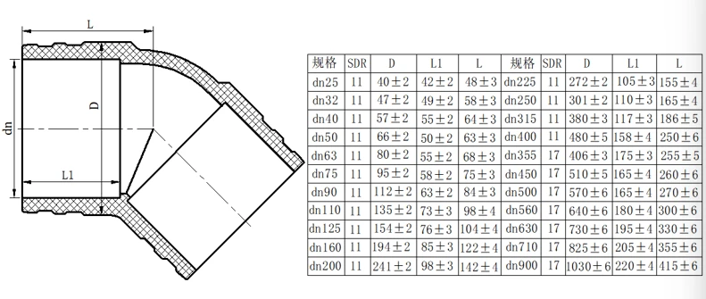
Section drawing: body outside diameter, leg length and centre-to-face length on the 45° body.
Head Loss: What a 45° Costs the Flow
This is the reason a 45° arrangement is specified even though it costs more in fittings. A long-radius right angle typically carries 0.6 to 0.9 velocity heads of loss through the turn. A single 45° bend carries about 0.2. A pair with a straight between them comes in near 0.4, which is a little over half the loss of the single right angle, and the gap opens up further as the sweep is lengthened.
Put plainly, the difference between 45 and 90 degree elbow is one of turn rate, not of function: the same job, spread over two fittings instead of one. The mechanism is not mysterious. A sharp change of direction separates the flow and puts a low-pressure zone on the inside of the bend, and that zone is where the loss is generated. Two gentler changes do the same total rotation but each one separates the flow less severely, and the straight between them lets the flow re-attach before it turns again.
Where the loss figure actually matters
On a district main where the operating pressure at the far end is already tight, the difference between 0.8 and 0.4 velocity heads can be the difference between a design that needs a booster and one that does not. On a short service connection the difference is academic. The figures are worth arguing over on pumped mains and on long transmission alignments, and are not worth arguing over on a meter chamber.
One Right Angle or a Pair of 45s
Search any 45 degree elbow vs 90 degree elbow question and the answers split into two camps: one says the pair costs more, the other says the loss is lower. Both are right and the trade is conditional. The comparison below is the one buyers ask for most often, and it is reproduced here because the answer is genuinely conditional rather than a rule. The trade is: one fitting and two fusion joints against three of each, a sharper and cheaper corner against a longer and flatter one, and a higher local loss against a lower one.
Where the single right angle wins
Chambers, valve pits and meter sets are built around a tight square corner, and there is neither space nor appetite for a swept alignment inside a chamber. A short service connection running from a building to a main is the same story: the footprint is small, the excavation is small, and the pressure is not marginal. In both cases the single fitting is the correct answer and the 45° is not.
Where the pair wins
A long pumped main has to turn somewhere, and the longer the line the more that somewhere matters. A pumped main is also the one case where 0.4 velocity heads instead of 0.8 is worth real money, because it either saves a booster or buys margin. An alignment that has to follow the ground rather than fight it is the other case: a swept turn grades through the obstructions a square corner would have to be aimed past.
| Decision point | One 90° elbow | Two 45° elbows and a straight between |
|---|---|---|
| Direction change | 90° taken in a single body | 90° spread over a longer, flatter footprint |
| Fusion joints added | Two | Three |
| Typical local loss | 0.6 to 0.9 velocity heads | About 0.4 velocity heads |
| Bending load at the turn | Carried by one fitting | Shared by two fittings and the pipe between them |
| Excavation at the turn | One tight corner, squared off | A shallow curve, graded through |
| Where it wins | Chambers, tight corners, short service connections | Long pumped mains and alignments that follow the ground |
| Purchase cost | Lower | Higher |
Where 45° Bends Go
The three places a 45° elbow earns its place are a shallow change of direction, a swept turn assembled from a pair, and a service or drainage connection. They are worth separating, because the sizing logic is different in each.
Gas distribution and the service end of the line
On a gas service the bend is usually a single 45° correcting the line as it approaches the main or rounds a boundary obstacle, and it is normally a moulded SDR11 size in the smaller diameters. What matters here is the wall series of the pipe it joins to, not the angle, and the fitting is ordered against the pipe, not the other way round.
Routes that have to follow the ground
A route that has to cross a ditch, follow a hedge line or work around a service without kinking is built from pairs. The 45° is the primitive; the designer chooses the straight between them and that choice is the curve radius. Longer sweeps suit gentle ground, shorter sweeps suit confined corridors.
Gravity drainage and process piping
Drainage and process lines use the same fitting with the sizing driven by the medium rather than by pressure. On gravity lines the loss figures matter much less than the ability to assemble a run from standard moulded sizes, which is the practical argument for having a 45° in the range at all.
Fusing and Backfill
Fusion is straightforward once the alignment is right, and the alignment is where the work is. Scrape the fusion face to bright plastic, dry it, and keep it clean - a dragged trace of soil is the most common cause of a joint that passes a visual check and fails under test.
Push the fitting home to the depth mark, run the barcode cycle, and leave it alone through the cooling period. A 45° is more sensitive than a straight to being disturbed early, because the misalignment it introduces is the same misalignment the operator cannot see once the joint is covered.
Thrust and the question of thrust blocks
A 45° bend does not eliminate thrust; it divides it. A pair of 45° bends produces two thrust vectors half a size apart in magnitude rather than one large one, and the two are partly resolved by the straight between them. Whether that is enough to avoid a concrete block depends on the diameter, the SDR and the test pressure of the line, and it is a question for the design calculation rather than for a catalogue.
Backfill and the first hours
Bury in the usual sequence, keeping the alignment intact during the first backfill layer, and check the offsets to the line before the trench is closed. A swept turn gives an installer more chances to introduce a kink during backfill than a square corner does, because there are three joints in it rather than two.
Moulding, Turning and Test
Both routes sit in one building. The moulding hall runs the PE100 tooling for everything to dn500, and the CNC turning cell next to it finishes the six large sizes from solid bar. A schedule that crosses from a moulded dn400 into a turned dn560 is a move between two cells rather than a shipment between two suppliers.
The laboratory is CNAS-accredited to ISO/IEC 17025 and works to three routine checks: coil resistance on every fitting, fusion joint strength, and dimensional inspection. The dimensional check is what confirms that a turned body landed on the published schedule, and it is the check that matters most on the six sizes which are not in the moulded range.

Injection moulding of PE100 electrofusion elbow bodies.

CNC turning cell finishing dn560 to dn900 bends from solid PE100.
Documents Held for This Range
The certificates below are the ones on file for this fitting family, listed with reference and expiry so a tender check can be made against the certificate rather than against a claim. Copies travel with the shipment on request, and the batch test record is issued per batch rather than per certificate.

Buyer Questions, Answered

Cartoned electrofusion elbows staged in the dispatch warehouse.
As the factory behind this 45 Degree Electrofusion Elbow, Qingfa Industry controls mould design, injection and final inspection in one place in Yuyao, Ningbo, China. Find out more about Qingfa Industry.
Hot Tags: 45 Degree Electrofusion Elbow | HDPE Gas and Water, PE100, 45 Degree Electrofusion Elbow | HDPE Gas and Water, PE100 dn25-dn900, 45 Degree Electrofusion Elbow | HDPE Gas and Water, PE100 SDR11/SDR17, 45 Degree Electrofusion Elbow | HDPE Gas and Water, PE100 dn25-dn900 SDR11/SDR17, PE100 45 degree electrofusion elbow | hdpe gas and water, pe100, 45 degree electrofusion elbow | hdpe gas and water, pe100 supplier, HDPE End Cap, End Cap HDPE Pipe, End Cap HDPE, PE PiPE End Cap, Electrofusion Test Cap, HDPE PiPE End Cap
You Might Also Like


Send Inquiry