



Asymmetric Bead and Pipe Misalignment in Butt Fusion Welding
Nov 09, 2026
Leave a message
A joint can be welded at the right temperature, for the right time, at the right pressure, and still be the weakest point in a pipeline. Misalignment does that. The two pipe ends sit off-centre, the bead comes out fat on one side and thin on the other, and the joint that looked acceptable at the end of the shift carries a bending stress nothing in the parameter record shows.
It is also the defect most often argued about on site, because there is no single number on a display that proves it. The evidence is geometric, it has to be measured before the plate goes in, and by the time the joint is cool the chance to correct it has passed. This page covers what the offset actually is, where it comes from, why the thin side is the one that fails, and how to tell an offset joint from a joint that merely has an uneven bead.
What misalignment actually is
Misalignment - offset, mismatch, hi-lo in some specifications - is the radial displacement between the two pipe ends at the fusion plane. In plain terms: the outside surfaces of the two pipes do not line up, so the wall of one sits partly in front of the wall of the other.
The measurement is taken on the outside surface, across the fusion plane, at the point of greatest offset. On a joint with a visible step, that is the depth of the step. It is not the difference in bead width, and it is not the gap at the facing - both of those are consequences, not the quantity itself. Measuring it properly means a straight edge or a dedicated alignment gauge held against one pipe, with a feeler or a taper gauge read against the other.
Two things make the number easy to under-report. First, the offset can be in any direction around the circumference, so a single reading tells you almost nothing; the joint has to be measured at four points at least, and the largest of them is the one that counts. Second, on a large diameter the wall is thick enough that a step which looks trivial in a photograph is well outside the limit when it is measured.

The ten percent rule and its blind spots
The joining documents converge on the same limit: misalignment at the fusion plane should not exceed 10 percent of the wall thickness. That single number is the acceptance criterion on most gas and water specifications, and it is the one an inspector can apply without argument.
The rule has three blind spots worth knowing about.
It is a percentage of wall thickness, not of diameter. On dn630 SDR 11, a wall of roughly 57 mm allows about 5.7 mm of offset. On dn110 SDR 11, a wall of roughly 10 mm allows 1 mm. The same 2 mm step that would pass unnoticed on the large pipe is a doubled overrun on the small one, and small diameter joints are exactly where a fitter is most likely to be working by eye.
| Wall thickness s, mm | Offset allowed at 10 percent, mm | What that looks like on site |
|---|---|---|
| 10 | 1.0 | A fingernail feel; invisible in daylight |
| 20 | 2.0 | Feels like a step, hard to see |
| 30 | 3.0 | Visible step, easy to measure |
| 45 | 4.5 | Clearly visible, often dismissed as a fitting tolerance |
| 57 | 5.7 | Obvious step, frequently passed without anyone measuring it |
The arithmetic is trivial and that is the point: the same physical step is a rejection on a dn110 wall and an acceptable joint on a dn630 wall. A crew that has been working on large diameter for a month and moves to small diameter will carry the wrong visual standard with them.
It is measured cold, before welding. The pipes move. A joint that measured 2 mm in the clamp can sit at 4 mm by the time the plate is out if one side is unsupported and settles. The check has to be repeated after clamping and after facing, not only at the first fit-up.
It does not account for angular misalignment. Two pipe ends can be perfectly concentric and still meet at an angle, producing an elliptical contact face, a bead that varies around the circumference, and a bending moment across the joint. Angular error shows up as a bead that is wide on one pair of opposing points and narrow on the other pair, with the offset measurement reading zero. Some specifications set a separate limit for it; many site procedures ignore it entirely.
Where a contract names a document, the limit and its measurement method come from that document, and the split between the two main families is covered in DVS 2207 vs ISO 21307.
Five sources of offset, and where each one starts
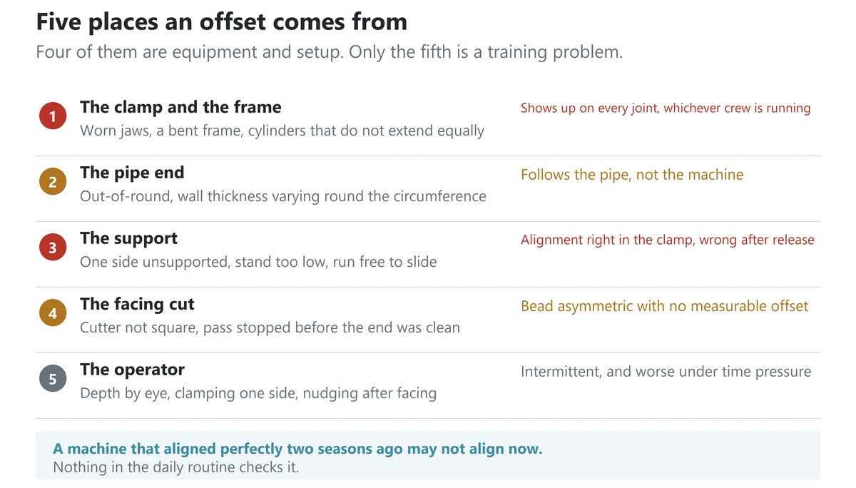
Misalignment is usually blamed on the operator. In practice it comes from five places, and only one of them is the operator's hands.
The clamp itself. Worn jaws, a bent machine frame, or hydraulic cylinders that do not extend equally will hold two concentric pipes off-centre. This is the source that gets missed because the machine is assumed to be right. It also develops slowly: a machine that aligned perfectly two seasons ago may not now, and nothing in the daily routine checks it. The relevant checks are in welding machine maintenance points.
The pipe end. An out-of-round end, a wall thickness that varies around the circumference, or a face cut at an angle all produce contact geometry that no amount of clamp adjustment will fix. Ovality in particular is a pipe property rather than a handling error, and it has to be dealt with before clamping rather than after.
The setup. Only one side of the joint supported, a roller stand set too low, a pipe run on a slope with no restraint, or a coil that still remembers being coiled - all of these let the pipe settle out of line once the clamp releases pressure. The joint is not welded crooked; it becomes crooked while it cools.
The facing. A cutter that is not square to the pipe axis, or a facing pass that stops before the end is fully clean, leaves one side with a different contact area. The result is a bead that looks asymmetric for a reason that has nothing to do with centring.
The operator. Insertion depth marked by eye, clamping force applied on one side only, the pipe nudged into position after facing. Each of these is a small decision made under time pressure, and each one moves the joint off-centre. This is the source that training addresses, which is why it belongs with the qualification discussion in welder qualification and operator training.
Why the thin side fails
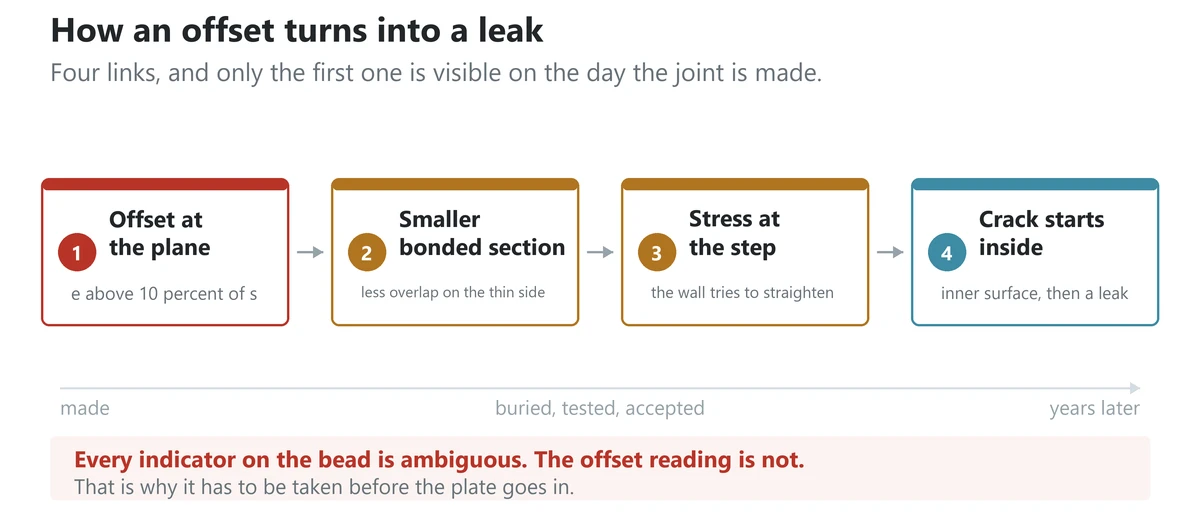
An offset joint has one side with a wide bead and one side with a narrow one, and intuition says the wide side is the strong one. The failure starts on the narrow side, and there are three reasons why.
Less material across the plane. The offset means the two wall sections overlap less on the thin side. The fused area there is smaller, so the load per unit of bonded area is higher. The bead is narrower for the same reason: there is less material being displaced across the face.
A stress concentration at the step. The step itself is a geometric discontinuity. Under internal pressure the wall tries to straighten, and the step acts as a hinge point, concentrating bending stress exactly where the bonded area is smallest. On a buried main the soil load adds a second bending component in the same place.
An unbonded strip that the bead does not reveal. When the offset is large enough, part of the facing on the thin side never comes into full contact during the joining phase. The bead still forms around it, because material is displaced outward regardless. What is left is a planar unbonded region near the inner surface, and it is the same defect class as a cold weld - covered in cold weld in HDPE butt fusion - except that here it has a geometric cause rather than a thermal one.
The combined effect is a joint that passes a short hydrostatic test, sits in the ground, and initiates a slow crack from the thin side years later. Because the initiation point is at the inner surface, the failure often appears as a leak before it appears as a rupture, which is the only forgiving thing about it.
An uneven bead is not always an offset joint
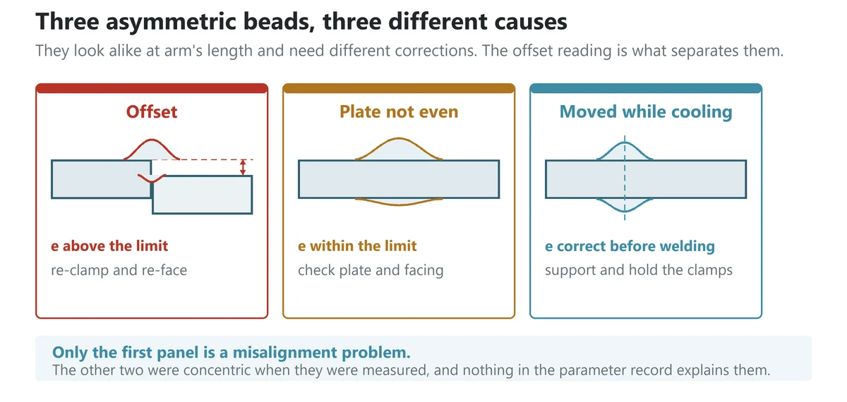
This distinction matters because the correction is different. A bead that is wider on one side than the other has at least four possible causes, and only one of them is misalignment. A fifth cause sits outside the machine altogether: two pipe ends that are not the same material. That case leaves the bead looking almost normal and the bond weak, and it is covered separately under material mismatch in PE pipe welding.
| Cause | What the bead looks like | What the offset measurement reads | Corrective action |
|---|---|---|---|
| Misalignment | Wide on one side, narrow on the opposite side, a visible step at the outside surface | Above the limit | Re-clamp, support, re-face, reweld |
| Uneven plate temperature | Wide and well formed on one side, flatter and duller on the other | Within the limit | Check plate surface at several points, clean the plate |
| Plate not seated evenly | One side shows a fuller roll, the other a shallow one, often with a mark where the plate touched first | Within the limit | Check the pipe ends for squareness, re-seat the plate |
| Movement during cooling | Bead pulled to one side, sometimes with a step that appears only after the clamps open | Reads correctly before welding, out after | Support both sides, hold the clamps to the full cooling time |
The fourth row is the one that gets misdiagnosed. The joint was concentric when it was checked, the parameters were correct, and the bead is asymmetric anyway. Nothing was wrong with the welding; the pipe moved while it was cooling. Recording the clamp release time and the support arrangement is what distinguishes this case from a genuine offset.
Checking alignment before the plate goes in
Alignment has to be verified at three moments, not one.
After the first fit-up. Both pipes in the clamps, ends brought together without pressure, offset measured at four points with a straight edge and a feeler. This reading catches a bent machine or a badly out-of-round pipe before any time is spent.
After facing. The facing pass can shift a pipe, particularly if the clamp was not fully tightened on both sides. Re-measure. A joint that was within limits before facing and out of limits after it will otherwise be welded without anyone knowing.
With the pipe supported as it will be during cooling. Roller stands set to the right height, the run restrained against sliding, and any unsupported span taken up. If the support changes between the check and the weld, the check was not valid.
The measuring tool matters less than the discipline of taking four readings and recording the largest. A dedicated alignment gauge is faster and more repeatable than a straight edge and feeler, but a straight edge used properly at four points beats a gauge used once. How much of this the machine checks for you depends on its clamps and frame rather than on its control class, though the classes differ in how much alignment they hold, as set out in semi-automatic vs fully automatic butt fusion.
Reading the bead after it cools
The finished bead is the only evidence left once the joint is out of the clamp, so it is worth measuring rather than looking at.
Bead width is measured at four points around the circumference, at the same clock positions used for the alignment check, and the spread between the widest and narrowest is recorded. A consistent spread on a joint whose offset was within limits points at plate condition or cooling movement. A spread that matches the offset direction points at alignment.
The other thing to read is the shoulder. A bead with a proper rounded shoulder on one side and a flattened, shallow shoulder on the other indicates that the two faces did not receive the same heat or the same pressure. That is a different defect from offset, and it belongs with the overheating and underheating failures rather than with geometry - the same family covered in over-fusion in PE pipe welding.
Sagging pipe: the cause with no entry in the log
On a long run, the pipe itself is the load. A dn400 SDR 11 pipe full of nothing still weighs enough that an unsupported span will deflect, and the deflection at the joint face is a few millimetres - which is the whole allowance on a smaller diameter and a significant fraction on a large one.
Sagging shows up in three ways. The offset reads differently before and after the clamps are tightened, because tightening lifts the pipe. The bead is asymmetric in the vertical direction, wide at the bottom or the top depending on which way the pipe dropped. And the joint is fine when it is made in the workshop and fails when it is made in a trench, which is the pattern that usually gets blamed on the crew.
The fix is mechanical and cheap: roller stands set so that the pipe axis is straight through the machine, a support close to the clamp on the unsupported side, and no restraint that fights the pipe's own weight. On a slope, the run needs to be held against sliding for the whole cooling period, not just during the weld.
Out-of-round pipe and wall thickness tolerance
Two pipe properties make alignment harder and neither is the welder's fault.
Ovality. A pipe that is not round cannot be held concentric by a round clamp without being forced, and forcing it stores strain that releases when the clamp opens. The practical test is a measurement at the same four points before clamping; if the out-of-roundness is significant relative to the offset allowance, the pipe needs re-rounding or the joint needs a different jointing method. On smaller diameters, re-rounding with an external clamp is routine. It is not a substitute for checking that the re-rounded section still meets the alignment limit once the clamp is released.
Wall thickness tolerance. PE pipe is manufactured to a tolerance, so the wall at the fusion plane is not exactly nominal. A joint between a thick section and a thin section has, in effect, a built-in offset even when the outside surfaces line up, because the inner surfaces do not. This is why the alignment check is specified as concentricity of the outside surfaces and the acceptance criteria are written against measured wall thickness rather than nominal. Where the mill tolerance has pushed the two sections far apart, the joint is a candidate for rejection on geometry rather than workmanship.
When the joint is already welded
If the offset is discovered after cooling, the options are limited and should be stated plainly: there is no field correction.
Re-heating does not straighten an offset joint; it makes a second, worse joint on the same pipe ends and consumes the stabiliser in the process. Forcing the pipes into line and holding them does not redistribute the bonded area. Adding a clamp, a saddle or a wrap transfers load but does not restore the missing bonded section.
The joint is cut out and remade with the alignment corrected at the source. The reason to say this early is that the alternative - leaving it in and hoping - is common, and it produces failures that are hard to attribute later because the parameter record looks clean. Where the joint is accessible and the consequence is high, non-destructive examination can at least establish whether an unbonded strip is present, as described in NDT inspection of HDPE welds. That turns an argument into a decision.
The wider set of defect mechanisms that a single joint can carry - and how they interact, since an offset joint is also usually a joint made in a hurry - is covered in HDPE pipe fitting defects and their causes. The sequencing that keeps alignment checks in the right order is in butt fusion fittings construction sequence. On fittings the problem is sharper still, because a spigot end has less length to hold in the clamp than a pipe, and the assembly order decides whether alignment survives to the cooling stage - covered in assembly method for butt-melted fittings.
What belongs in the checklist
- Measure offset at four points after fit-up, after facing, and with the pipe supported as it will be during cooling. Record the largest value.
- Compare the reading against 10 percent of the measured wall thickness, not the nominal.
- Check the machine's concentricity at the start of each shift, not once a season.
- Support both sides of the joint to the same height, and hold the run against sliding for the full cooling time.
- Do not open the clamps early to save time. Most asymmetric beads with no offset were made this way.
- Re-round oval pipe before clamping, then re-check alignment after the clamp is released.
- Measure bead width at the same four points and record the spread.
- Reject on geometry rather than argument. An offset joint cannot be reworked into a concentric one.
The parameter side of the process - what the plate, the pressure and the clock are supposed to be doing while the pipe is held straight - is covered in the PE pipe fusion welding guide and in how to calculate butt fusion pressure. The weather chapter matters here more than it looks: a hot day softens a pipe run and lets it sag between supports, which is covered in welding PE pipe in rain, heat and cold.
Frequently asked questions
What is the maximum allowable misalignment in HDPE butt fusion?
Ten percent of the wall thickness is the figure common to the main joining documents, measured on the outside surface at the point of greatest offset. Some specifications tighten it for gas service or for large diameters, and some express it as an absolute value for small pipe. Where a contract names a document, that document governs.
Can an asymmetric bead be caused by something other than misalignment?
Yes, and more often than not it is. Uneven plate temperature, a plate that did not seat flat against both ends, and movement of the pipe during cooling all produce an asymmetric bead on a joint that was concentric when it was checked. The offset measurement is what separates the cases.
Is a wide bead on one side stronger than a narrow one?
No. The wide side has displaced more material outward, not bonded more area inward. The load-bearing section is set by the overlap of the two walls, and the thin side is where that overlap is smallest and where the step concentrates stress. Failures initiate there.
Does the pressure calculation change when the joint is misaligned?
The calculated interface pressure does not change, because it is derived from the nominal wall thickness and the ram area. What changes is the actual stress in the joint, which is higher than the calculation assumes. That gap is why alignment is an acceptance criterion in its own right rather than something absorbed into the pressure setting.
How do I check alignment on a joint that is already buried?
The external bead is the only accessible evidence. A bead that is markedly asymmetric in a consistent direction, with a wide side and a narrow opposite side, justifies excavation and examination. Internal inspection or ultrasonic examination can establish whether an unbonded strip exists; the bead alone cannot prove it.
Why does the joint go out of alignment after the clamps are released?
Because the pipe was being held in position rather than resting in it. An unsupported span, a roller stand set too low, or a run that was pulled into line during fit-up will all spring back once the clamp pressure is removed. The check that matters is the one taken with the support arrangement that will be there during cooling.
Send Inquiry